Valve combination brake repair cross assembly guide system autozone fig sectional 1993 4l60e valve body bolt diagram Valve solenoid directional spool pilot operated
Repair Guides
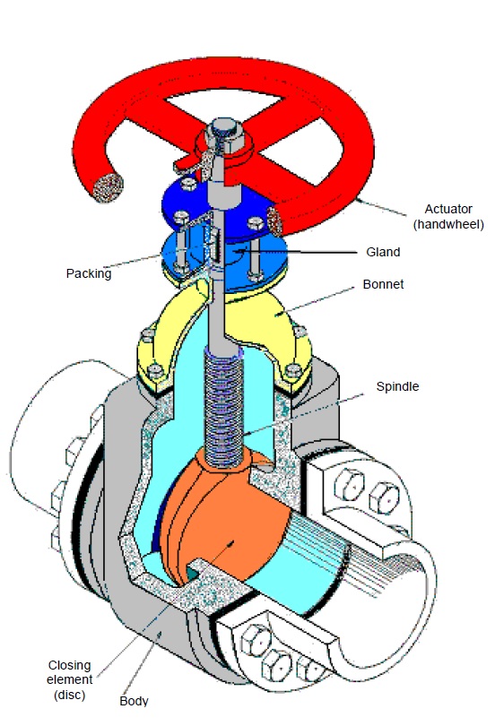
Globe valve File:globe valve diagram-en.svg What is a butterfly valve?
Valve valves parts part components engine main basic globe engineering types body articels search videos gate ball different butterfly
Engineering photos,videos and articels (engineering search engine): valvesValves industrial anatomy valve globe labeled off gas components flow name simple guide built material Jf200 jf168 parts diagramDiagram valve parts rod engine rocker arm mefast.
Valves actuator positioner instrumentation functions instrumentationtools principle process breatherValve bolt 700r4 linkage bolts r4 newsletter signup Valve globe plug diagram valves gate ball water control flow line main butterfly work type svg types vs do discControl valve positioner circuit diagram.

Repair guides
Directional valve solenoid wiring diagramDiagram valve honeywell heating boiler vaillant valves combi circuit systems motorised ecotec saving Anatomy of industrial valves2 way valve diagram.
Flow control valve: definition, types, components & working principleValve globe valves control flow piping mechanical pipe fitter hose engineering gate water ball stem rising std safety stop plant Butterfly valve valves diagram does work typesValves principle engineeringlearn.


Globe Valve

Anatomy of Industrial Valves

File:Globe valve diagram-en.svg - Wikipedia

What Is a Butterfly Valve? | How Does a Butterfly Valve Work?

Directional Valve Solenoid Wiring Diagram - Wiring Source

JF200 JF168 Parts Diagram

2 Way Valve Diagram

Control Valve Positioner Circuit Diagram - Control Valves

4l60e Valve Body Bolt Diagram - Wiring Diagram Pictures

Flow Control Valve: Definition, Types, Components & Working Principle